Manufacturing & Quality
4.0 factories, automation, validation
Partner Portal
Access tools, pricing, ESG data

Architecture Selector: Which ATOP Product Fits Each Network Path
| Network Architecture | Network Infrastructure | NVDIA P/N | ATOP P/N | Description | Application |
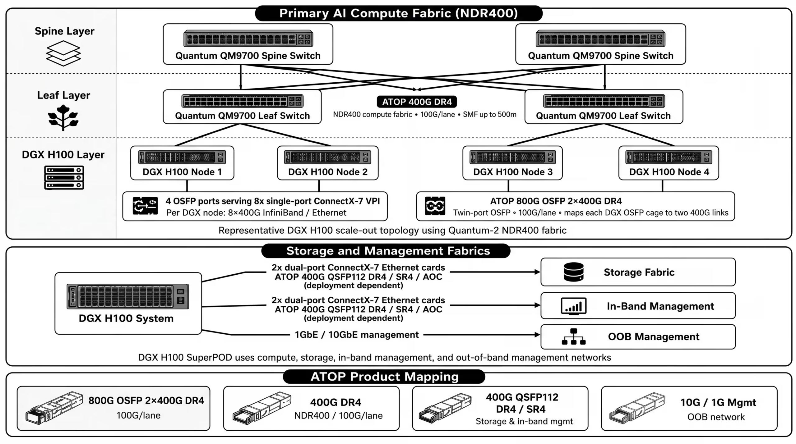
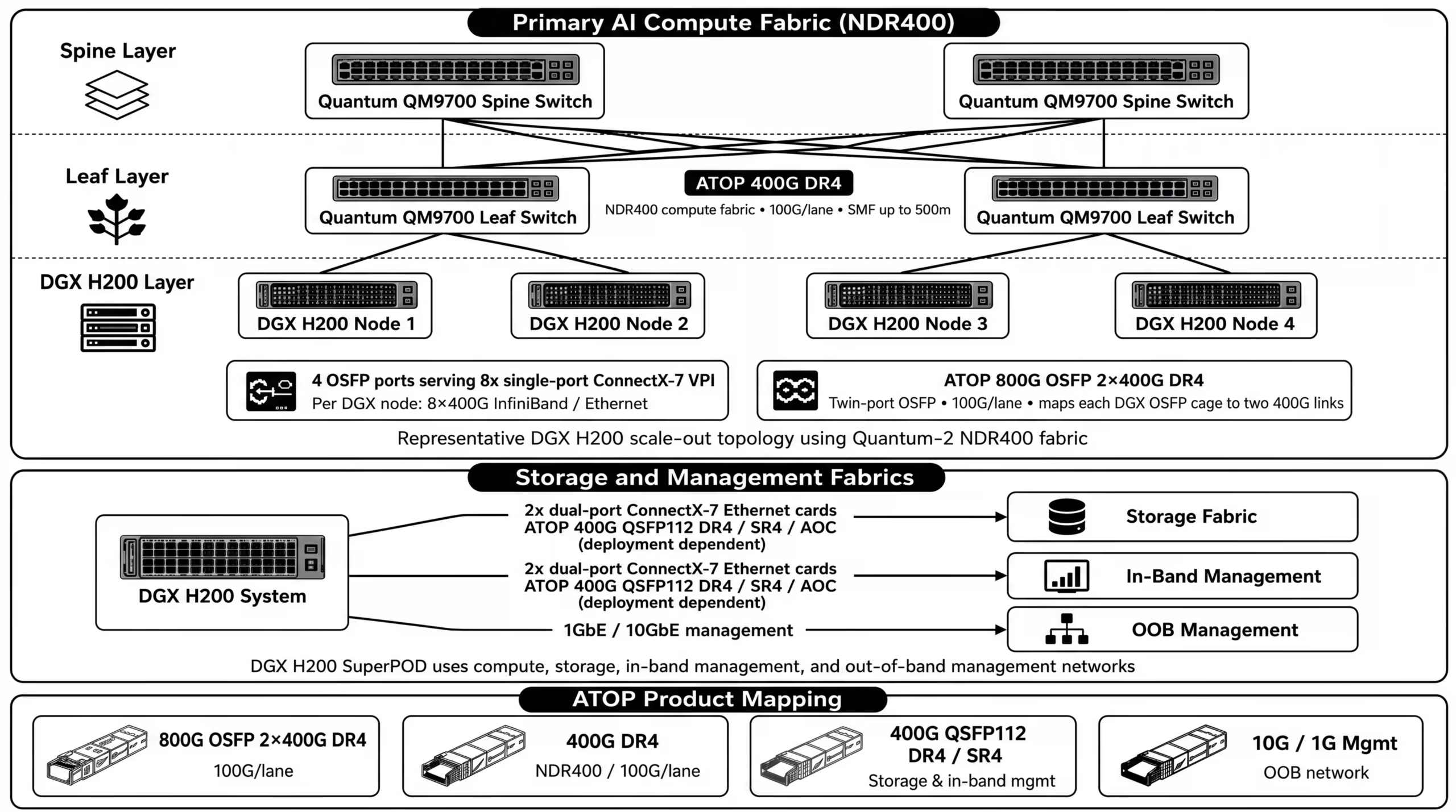
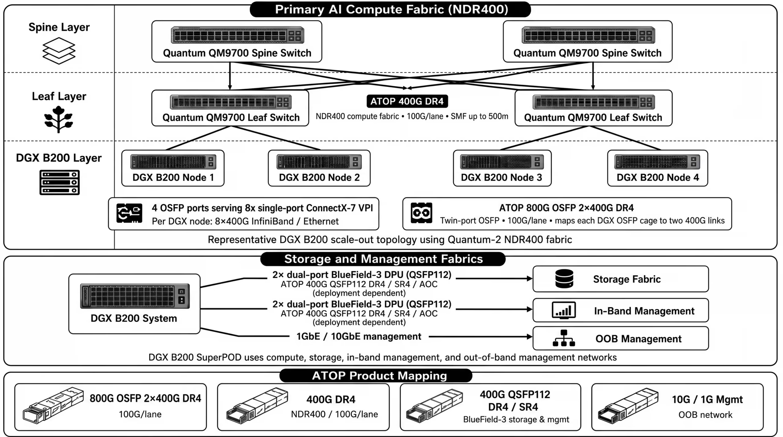
| H100 / H200 / B200 SuperPOD | Quantum-2 NDR400 + ConnectX-7 | MMS4X00-NM MMS4X00-NS400 MMS1X00-NS400 | APOP31KCDMD8T APOP31HCDMD4A APQPB31KCDMD4A | 800G OSFP 2x400G DR4 400G OSFP DR4 400G QSFP112 DR4 | Compute fabric and 400G links |
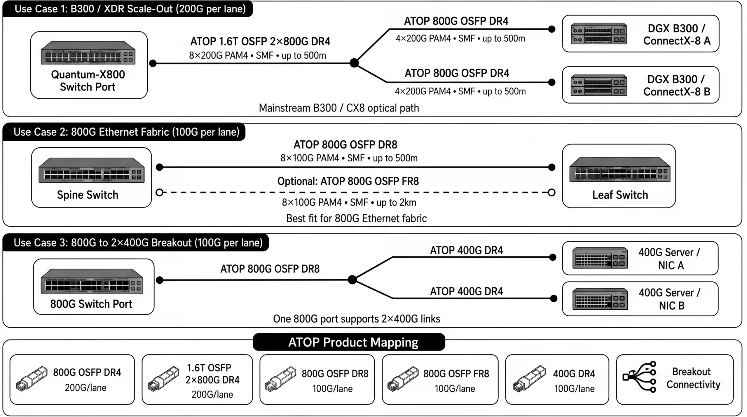
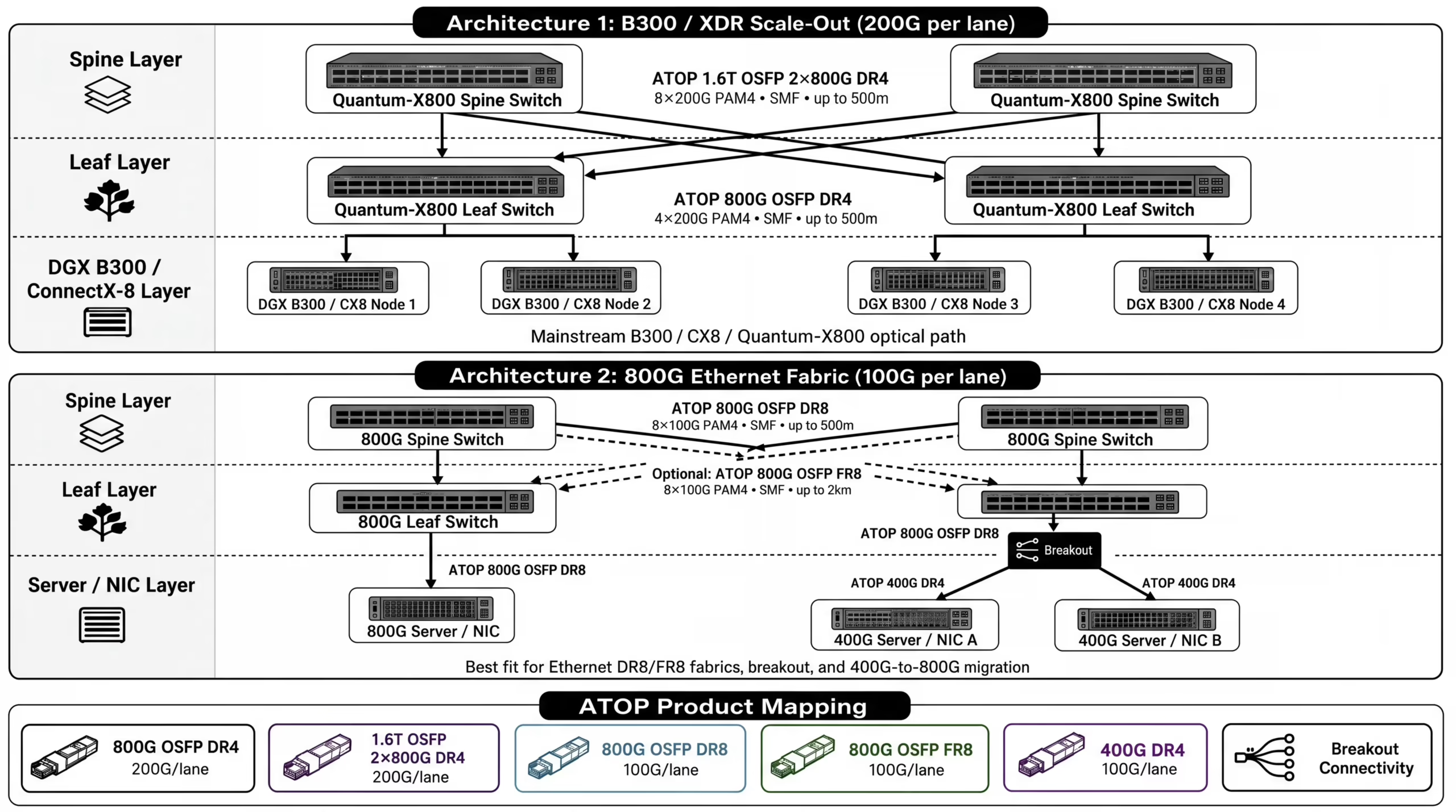
| B300 deployment | ConnectX-8 + Quantum-X800 XDR | MMS4A20 MMS4A00 MMS4X00-NM16 MMS4X50-NM MMS4X00-NS400 MMS1X00-NS400 | APOP31KCDMD4C APOP31KCDMD8E APOP31KCDMD8R APOP31KCDLF8F APOP31HCDMD4A APQPB31KCDMD4A | 800G OSFP DR4 1.6T OSFP 2x800G DR4 800G OSFP DR4 800G OSFP 2xFR4 400G OSFP DR4 400G QSFP112 DR4 | Server-to-leaf and XDR fabric |
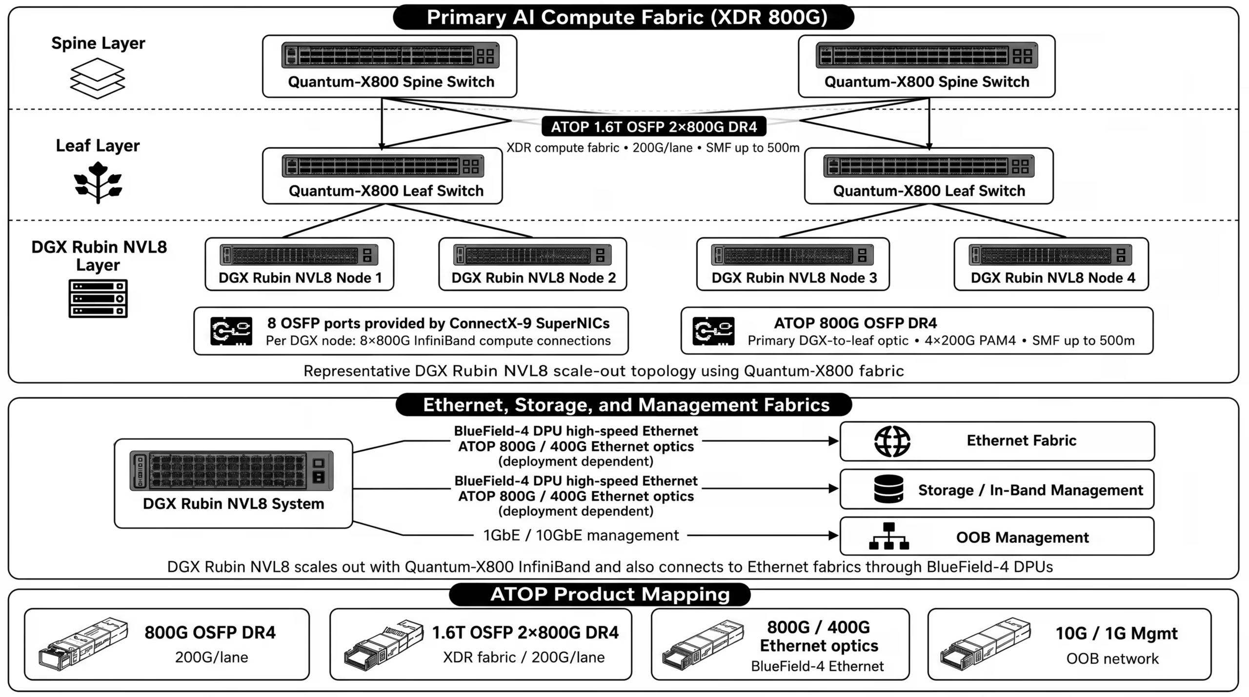
| Rubin NVL8 / XDR | ConnectX-9 + Quantum-X800 | MMS4A20 MMS4A00 | APOP31KCDMD4C APOP31KCDMD8E | 800G OSFP DR4; 1.6T OSFP 2x800G DR4 | Scale-out compute fabric |
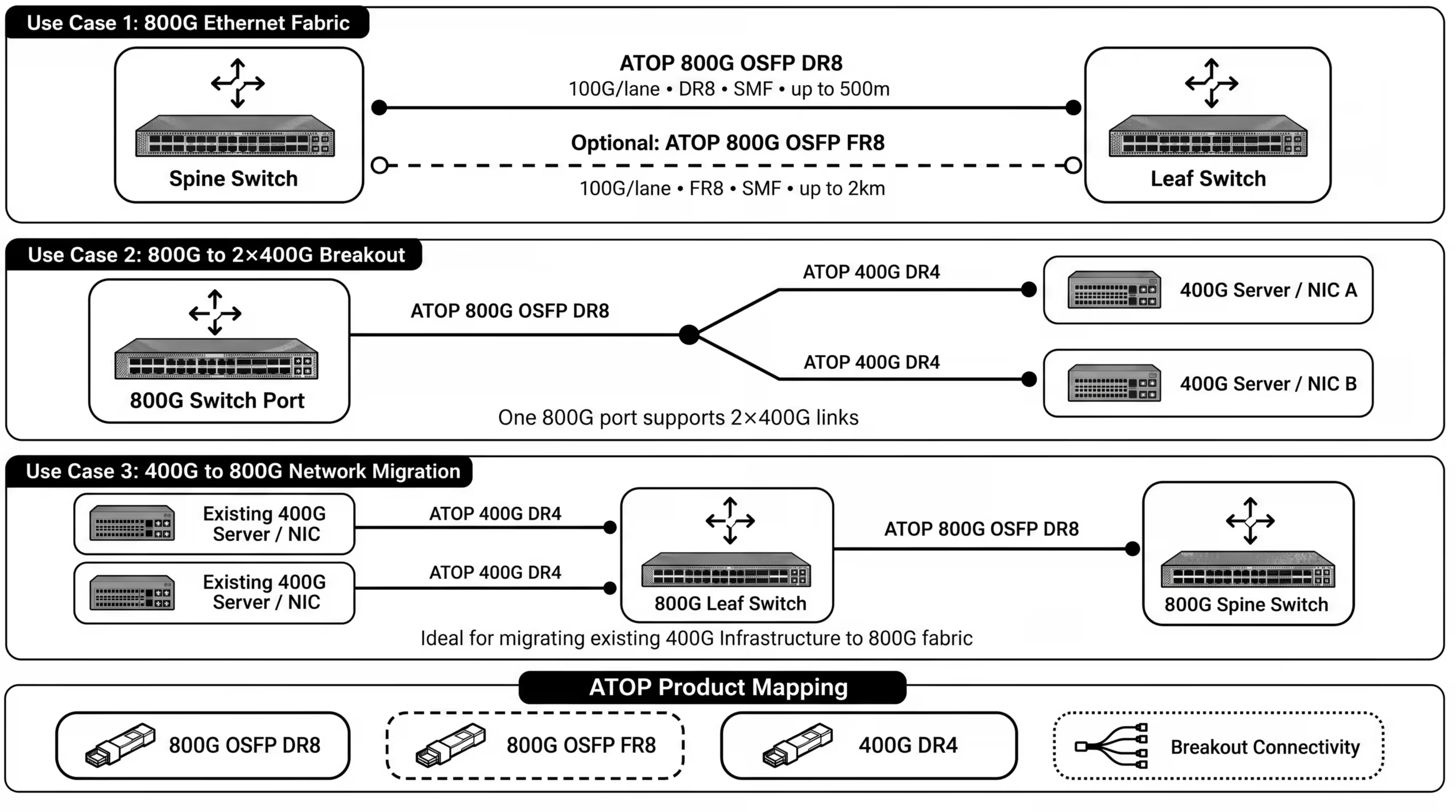
| 800G Ethernet fabric | Spectrum-X / 800G Ethernet leaf-spine | MMS4X00-NM16 MMS4X50-NM | APOP31KCDMD8R APOP31KCDLF8F | 800G OSFP DR4 800G OSFP 2xFR4 | Switch-to-switch, leaf-spine |
| 400G-to-800G migration | Breakout from 800G switch ports | MMS4X00-NM MMS4X00-NS400 MMS1X00-NS400 | APOP31KCDMD8T APOP31HCDMD4A APQPB31KCDMD4A | 800G OSFP 2xDR4 400G OSFP DR4 400G QSFP112 DR4 | 2x400G breakout and staged migration |
| Storage / in-band management | BlueField / Ethernet storage fabric | MMS1X00-NS400 MMS4X00-NM16 | APQPB31KCDMD4A APOP31KCDMD8R | 400G QSFP112 DR4 800G where required | Storage and management traffic |
Rule of thumb: 100G/lane optics remain central for NDR400, DR8/FR8 Ethernet and breakout. 200G/lane optics are the forward path for B300/Rubin class XDR deployments. ATOP supports both paths, which helps customers avoid a single-generation product gap.
| Operating conditions | Lane | Voltage[V] | Value | Unit | Verdict |
| Differential Output Voltage | L1 | 3.3 | 524.16 | mV | Pass |
| Eye Height | L1 | 3.3 | 69.83 | mV | Pass |
| Near End Eye Width | L1 | 3.3 | 17.21 | PS | Pass |
| Far end ISI | L1 | 3.3 | -5.38 | % | Pass |
| ESMW | L1 | 3.3 | 0.16 | UI | Pass |
| Electrical Transmitter | Spec Min | Spec max | units |
| Differential Voltage, pk-pk | 900 | mV | |
| Far End ISI | -4.5 | 2.5 | % |
| ESMW | UI | ||
| Near-end Eye Width at 10-6 probability (EW6) | 4.99 | ps | |
| Near-end Eye Height at 10-6 probability (EH6) | 70 | mV | |
| Far-end Eye Width at 10-6 probability (EW6) | 3.76 | ps | |
| Far-end Eye Height at 10-6 probability (EH6) | 30 | mV |
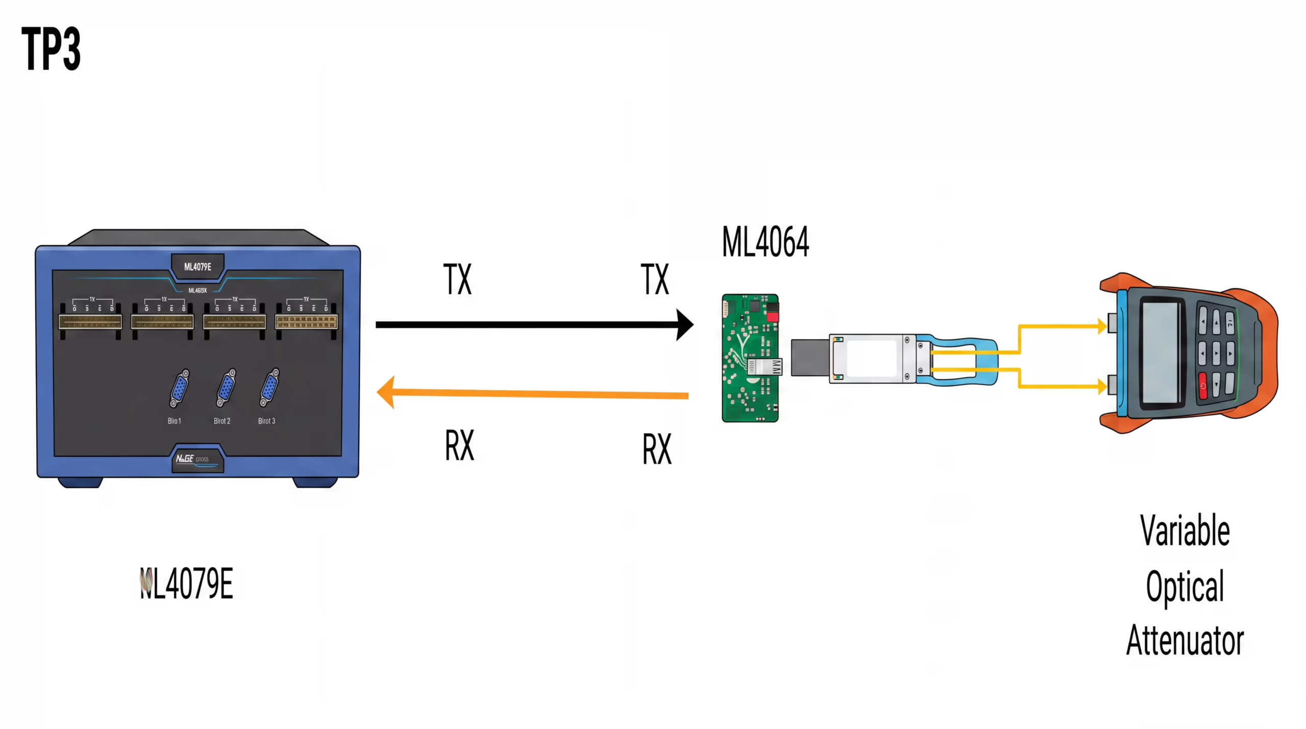
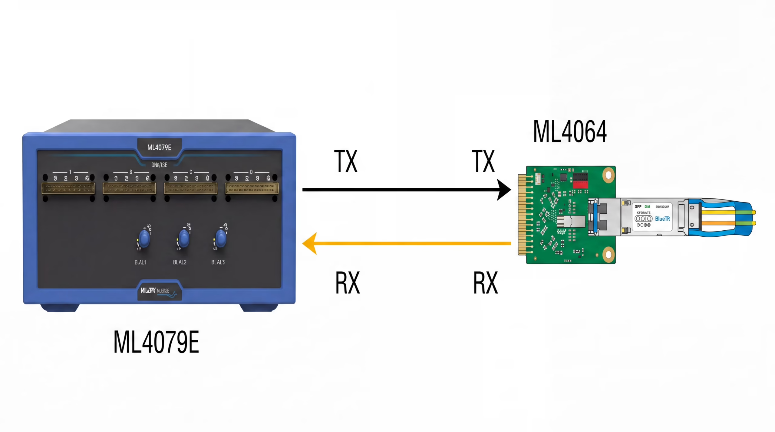

| Category | Test Results & Observations |
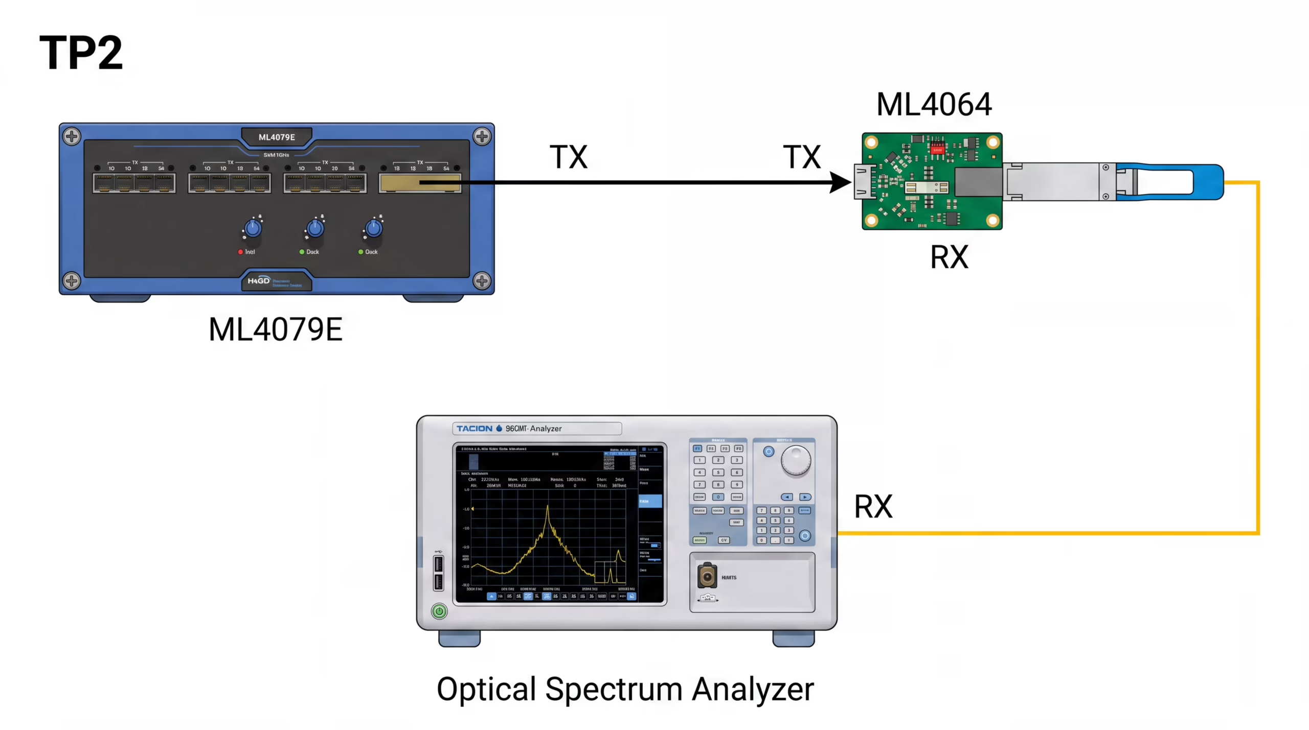
| Optical | DOM values within expected ranges; no unexpected alarms; clean eye/TDECQ margin where tested |
| Electrical | Stable high-speed output/receiver behavior across the tested host profile |
| Protocol | Correct application advertisement, channelization and breakout profile |
| Traffic | Stable line-rate traffic; acceptable pre-FEC BER; zero uncorrected FEC codewords |
| Operations | Hot-swap, reboot, fiber pull and link flap recovery without abnormal behavior |
| Thermal | Case temperature within target envelope under actual rack airflow |
| Platform / Reference | Documentation Summary |
| H100 / H200 | NVIDIA DGX H100/H200 user guide: 4 OSFP cluster ports serving 8 ConnectX-7 single-port cards; up to 400Gb/s InfiniBand/Ethernet. |
| B200 | NVIDIA DGX B200 documentation: 4 OSFP ports serving 8 ConnectX-7 VPI; BlueField-3 DPUs for storage/management. |
| B300 | NVIDIA DGX B300 documentation: 8 OSFP ports serving 8 ConnectX-8 VPI; up to 800Gb/s InfiniBand/Ethernet. |
| Rubin NVL8 | NVIDIA DGX SuperPOD Rubin NVL8 reference: 8 OSFP ports provided by ConnectX-9 SuperNICs and BlueField-4 Ethernet connectivity. |
| 200G/lane optics | NVIDIA MMS4A20 documentation: 800G DR4, 4-channel 200G-PAM4, MPO-12/APC, SMF up to 500m. |
| 100G/lane optics | NVIDIA MMS4X00-NM documentation: 800G 2xDR4, 8-channel 100G-PAM4, 500m reach and 17W max power. |
| Longer reach | NVIDIA MMS4X50-NM documentation: 800G 2xFR4 / 2x400G, LC duplex, 2km reach. |
| ATOP validation | ATOP-supplied third-party ODVT and switch interoperability reports for 800G OSFP DR8 and 400G QSFP-DD DR4. |